Saturday, May 14, 2011

Brake calipers - 1st Round

After a weekend without car-time due to an unexpected work spike, today I had 2 hours to spend. Full of expectations, took to the car the rear disks and the box with all calipers and associated parts.

Placed the rear disks on the hubs and bolted them in place with the wheel nuts. Then bolted in the caliper supports (guides?), putting loads of thread-locking "Pattex Nural" on the bolts. Finished off by cleaning all the disks with disk cleaning spray.
Then assembled the front caliper. In February I tried assembling them at home and had some doubts. The people on the locostbuilders.co.uk forum weren't helpful on this topic (which was odd) and I ended up finding how to assemble an M16 caliper through some reading and pictures on the caffetine site. Using some old pictures I took back in February below... I put some copper grease between the plates and the pads (careful not to compromise the pads friction area). Then placed the clips on the pads and plates and inserted it all on the caliper. Placed the shafts through the holes and the locking clips on it's tip. The pads had arrows that point on the direction of wheel spin. The caliper must be placed with the bleeding hole (currently has a sort of sticker stating that it's a reconditioned item) on the inside top.
It all looks great but when I went to bolt it on the car the disk didn't fit between the pads. There must be something I should have done on the calipers to retract the pistons a bit more before assembling the lot. Left the other front one unassembled. Opened the box that had one rear caliper and couldn't figure out how to assemble it. Called it a day and will have to investigate a bit more before next weekend.

Sunday, May 1, 2011

Proper Tools...

Having proper tools makes all the difference. Last week I bought new good drill bits and a vise grip. Today, the three hours spent really were worth it.

Forget about all the time spent with drill bits and enlarging holes. New top bit for 8mmØ and in no time finished the hole for the 1st bolt and drilled the 2nd one to get the handbrake lever in place. Also had with me the 2nd set of alan keys so I tightened the gear lever.
I got some tips from the locostbuilders forum about how to solve my issue with the front steering link shafts rotating when I tried to tighten the nuts. I should jack up the link to apply pressure and the shaft would stop spinning. I didn't have a jack but placed my knee under it and applied some upwards force and it was enough to tighten the nuts.

Went on the back and using the vise grip and some cardboard to protect the thread on the shaft, finally managed to loosen up the nut and center the shaft on the rear hub. I needed a wheel to see if it was good or not...

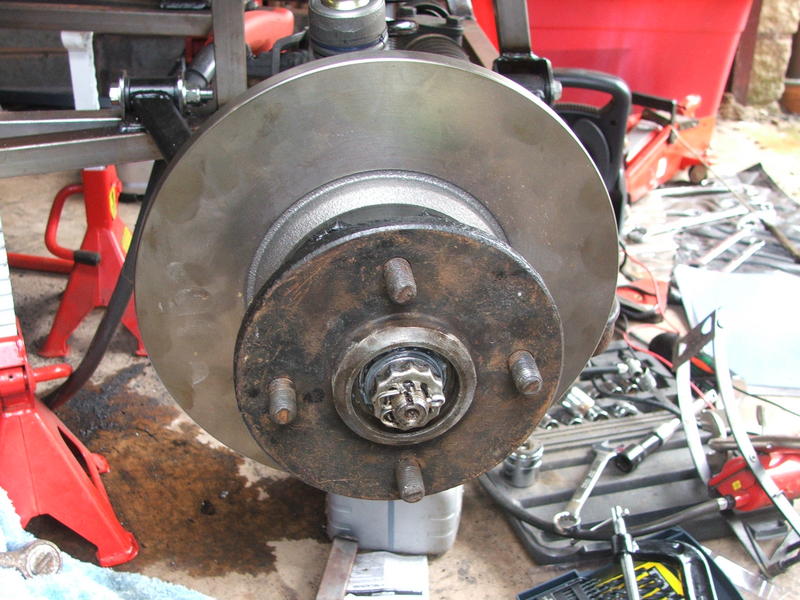
Back to the front, placed the disks and calipers (previously bolted together) on the hubs. Tightened the nuts and placed the castle nuts. The split pins were home...
Went upstairs to grab a wheel, the split pins and hub covers and the rear disks. Back on the car placed the split pins on the front hubs. The picture doesn't show it well but the castle nut resembles a castle tower top and the split pin goes in a hole and I split it around. You can see a better picture here. Then I filled the caps with grease and placed then over the pins.
Trial fitted the wheel on the front. Since I didn't put any nuts, it tilts and looks like there is a lot of negative camber. But it looks nice!
Took the wheel to the back and trial fitted it on the rear side to test my prior work. It still rubbed inside the wheel. Probably spent one hour getting it to a point where I was content with the result. Summing it up... 1) completely removed the shaft; 2) removed a couple of washers from between the back of the hub and the bush; 3) Refitted the shaft with those washers between the front rose-joint and the hub (moving the center of the wheel to the back to help out); 4) removed the washer between the bush and the nut to get 1mm less shaft to the back without actually reducing the number of threads; 5) reduced the number of threads.

I'll have to see with the brake disk in place. It doesn't rub the wheel but it might rub the weights that are glued to the inside of the wheel, to balance it. But if that happens, I'll just move the weights a bit to the side. I'm tired of fighting that particular issue.

Last word for the great vise grip I bought. I've been bitten back too many times with cheap or chinese tools and materials. This time I went to a proper tool shop. The guy showed me two tools, a chinese-alike one and a proper one. 5€ and 17,50€. Loved the fact that he spoke about how better the good one was but didn't just shove it down my throat. Bought the good one and was offered a lesson about how to use it (which I really needed). Today, after all the use I gave it and how wonderfully it behaved, don't regret it a bit.

Wednesday, April 27, 2011

Tightening Hubs

Spent an hour and a bit on the car. First swapped nuts from two bolts. There were 4 nuts with just 2 "cuts" on their faces, that were shorter than the others. Another builder told me last weekend they should be used on the upper shock mount bolts. Two were right (the front ones) and two were wrong (the back ones). Fixed that.

Then spent some time trying to hold the bottom pivot of the rear upright with pliers, protecting the thread with cardboard, so that I could undo the nut on the other side. Failed. I really need a proper tool, a vise grip I guess. Considering instead of spending on the tool to just take the pivot out and insert it the other way around, with the bigger part to the front of the car, since that way it will not rub on the inside of the wheel. But that's the easy (and lame) way out, I guess...


Last task was tightening the nuts on the front hubs that hold the ball joints and steering arms. The upper and lower ball joints were easy. The steering links I couldn't tighten. The threaded shaft rotates and I don't see how I can hold it in place...


Still unsure what I'll take as the next task, but it seems it can't be anything on the wheels unless it is something to solve my problems above.

Friday, April 22, 2011

Shifting!

I had been checking the web for pictures of other Aries or Stuart Taylors to see how the gear pivot was placed. I noticed that no one had the lower shaft on a 90º angle with the footwell chassis tubes. Maybe I could still use the holes I started drilling... So I undid the bolts that linked the lower pivot to the engine but it was no good.

Marked new places for drilling, got it done, some more filing on the gear knob and it all became assembled!
Jumped inside the car making engine noises and shifting gears. Then I realized I don't know how to really shift gears (forward moves me from 1st to 6th or is it the other way around? and where is neutral?). Jumped out, fiddled with the clutch cable nuts to make the clutch harder and then turned around the bolts that hold the pivot on the passenger footwell to make it look nicer. And there we have it, another major task done!

Last task was to drill holes to hold the handbrake lever. Measured, drilled the first hole with the 4,5mmØ so that I could then enlarge it with the 10mmØ. The idea was to then put the lever in place and drill the second hole with it there, so that I wouldn't miss it. Turns out that the chassis rail I have to drill is resisting the 10mmØ cheap drill bit. And it also resisted the 8mmØ cheap one I tried to make it in three stages. So I packed up and finished for the day. I'll be buying quality 6, 8 and 10 mmØ bits before going on the car again.

Sunday, April 17, 2011

Measure Once, Drill Twice

Only had about one hour and a half this weekend and managed to make it a bad time.

Started nicely by tightening up the bolt and nut that hold the clutch cable on the peddle (that was only hand tightened before). That went well.

Next task was to file a bit the gear lever on the sides so that it would fit inside the tunnel walls. It took a bit, since I was doing it manually, but it got done.

Then I sat on the car pretending to be driving to set where I wanted to drill for the gear lever. Ends up I forgot to double check and use something to mark each position or test. The linkage that goes from the lever to the top of the pivot can be somehow adjusted in length. But only to some extent. After drilling both tunnel chassis tubes side to side with a 3,5mmØ and then enlarging them with a 6mmØ (that still has to be enlarged to 8mmØ), I made a test fit and noticed that I drilled 2cm too much to the front than what the linkage can be shortened...

Now, I have two options... Try to make it fir having the pivot stand not in a perpendicular form (if that works) or re-drill in another place.

I'm very mad at myself. It's not a visible mistake, since panels will cover up. But I feel I weakened the chassis and list (precious) time because I didn't pay enough attention to detail or the task at hand.

More to follow next weekend...

Sunday, April 10, 2011

Gear Linkage

Drilled and applied the rivets I didn't do last weekend. This time besides eye protection and ear mufflers while drilling, also used gloves when using my big rivet pliers to avoid bleeding from knuckles when hitting the chassis. I should get some ISO certification for work safety!

After that I drilled to bolt the rotating arm that supports the gear changing mechanism. One if it's bolts goes through the chassis, the other bolts on the ally panel. Pretty straight forward. Spent some time fastening all the bolts on the linkage. It was my plan to do all the linkage and then sit on the car shifting gears. Unfortunately, had lunch arrangements and had to leave with just two holes to drill for the gear lever...
(Barely) Visible in the photo is the fact that I bolted with the bolt head inside the engine bay. Should have done it the other way around, for a better finish inside the passenger footwell. Sometimes it seems I'm not paying attention to detail. Will have to do those bolts again next weekend.

Last week swapped some emails with Steve from Aries about my current tasks at hand. He was not sure I would be able to fit the panel and linkage without taking the engine out, usually people only put the engine in later in the build. Thanks to my 90º drill extension, I managed to drill in tighter spots, so I got it without touching the engine. Was very happy with that.

I think that after doing the gear lever, I'll get the throttle peddle just for the kicks, and postpone pipes a bit more...

Sunday, April 3, 2011

Passenger Footwell Ally Panel

Spent this weekend car time riveting the passenger footwell ally panel. The panel was partially glued with what I managed to extract from the PU stuff last weekend. It helped a bit to keep the panel in place.

Unlike previous rivets (pipework), these 4,8ø rivets were thick and hard. When I tried to rivet my first one, didn't have enough strength! Had to use both hands and squeeze them between the legs to get the rivet in place. These were not like the 3.2ø rivets and I was anticipating a hard and long session. After some 5 rivets, I no longer managed to do it. It even seemed like I was bending slightly the rivet pliers.

That was when I recalled a day in May 2010, when I visited Steve at Aries, during my process to select the kit car to order... He was giving me tips about building, showing me doing a kit car is not that hard and how he could prepare stuff to make it even easier. Then he grabbed his "heavy duty rivet pliers" and said that one of the best advices he could give me was to buy one of those. I had one that my wife had offered me on my birthday. Went upstairs to grab it and... It made all the difference!

After that it was just trying to juggle such a big plier between chassis and engine and go around applying the rivets. Didn't manage to finish it but before packing up I assembled the gear linkage to see where it would need to be bolted to the chassis. Had to fight a big urge to sit on the driver's place and pretend to be driving and shifting gears... This is bringing up the kid I have inside.