Sunday, November 24, 2013

Nosecone Is ON!

As planned, spent the initial period of this week's car time looking into the indicator's electrics. In the end, destroyed 1h30m of work that I was not happy with and will wire the wing indicators from the loom terminals near the scuttle, using long cables. And the nosecone indicators are plugged where they should, in the front end of the loom.

Liberated from that hurdle, prepared the nosecone to be fit. Had to file slightly the holes on the fiberglass to match them with the ones on the chassis and tape the indicator wires so that they would be somewhere I could reach. After that, just fit the thing, a bit more filing and bolted down the 4 bolts. It took the doomed-headed-squared-oddities near where the hood will fit and two that look like wood bolts with washers through the fiberglass and chassis, near the headlight beams.
I'm very happy with how the car ir looking. After taking the photo placed some bubblewrap over the fiberglass, since I cover the car when not working on it and don't want the cover to scratch the fiberglass.
Next week will be attaching the scuttle and marking the hood for cutting (because of the airbox).

Saturday, November 16, 2013

Aeroscreen and Electrics

Started this session by fitting the aeroscreen on the scuttle. Not as hard as I thought it would be. Took the time to also drill the four holes on the bottom that will bolt down to the chassis.
After this was done, trial-fitted the nosecone and marked for drilling the chassis near the headlights. Drilled the holes and then spent some time working on the electrics.
I believe I mentioned when I attached the headlights to the loom that it was temporarily done (butchered). These are now correctly connected to the loom with bullet terminals on the wires.
Also looked on how I'll do the indicators but did not start the work. The problem here is that, when I bought the car, there were indicators on the nosecone, the sides of the scuttle and the rear. Since then IVA rules changed a bit and now I need to have them on the nosecone, front wheel wings and rear. This means that the loom terminals near the scuttle must be abandoned and the ones in the front used for both nosecone and wings indicators. Since I don't have a big variety of connector types, I have to be a bit creative doing this. The plan is drawn, just need to do it before fitting the nosecone (for ease of access to the wires)

It was a good session and I'm eager for the next, since I'll end up with the nosecone on the car, if all goes well. Maybe even with the scuttle too!

Sunday, October 20, 2013

Rear-view Mirrors

Almost a month and a half later, I'm back working on the car. Several other things got in the way but the three hours spent today were very good.

Last weekend I had some friends over and they wanted to see the car working. So I took each one of the three for a couple of laps around the garage. It was fun and now I have my fuel tank almost empty.

First small job today was to try to tighten the front lights since they were really lose. I don't have a deep socket so I used pointy pliers, otherwise would have to go shopping. The pliers did the trick. Then I separated the scuttle from the dash panel and left the dash on the car. The scuttle was taken to the storage room where I drilled a few holes (after lots of measuring) to put the rear-view mirrors in. This is the final look:
I think the side mirrors may be switched around, will have to look better into it. The kid came around as I was finishing up so it was him, eager to help, that tightened all the mirror's bolts.

Next task will be to drill the holes below to fit to the chassis and put the "tiny windscreen".

Sunday, September 8, 2013

Finish the Nosecone

(long overdue post, this work was done almost a month ago, I haven't been able to work on the car lately; hope next week...)

Today I was committed to finish the nosecone. First I had to drill the sides for the bolts that connect with the chassis near the hood. These are doomed bolts that have a square section at the rear. Since I don't have a Watts drill to make square holes, did it the hard way. First drilled a round hole. Then, with a small file, squared the hole until it was a snug fit.
Then it was time to drill for the indicators. First I remeasured the drilling spots, using a level to be sure the nose was sraight before measuring. Placed again paper stalks just to get an idea. Then I drilled the big hole for the indicador hollow bolt through which the wire goes and a smaller one for some sort of guide that helps ensure the indicator is in the right position. Indicators bolted and job done!
Since I had the driller around, drilled the two holes on the lip almost where the rear of the nose goes down (over the area where the light stalks are), where other bolts will go through and attach to the chassis. The only thing missing is to drill the two holes on the chassis. The kid has been asking me to come help, so I'll probably let him drill those holes.

Saturday, August 31, 2013

Start On The Nosecone

After some time away due to vacations, I was back for a bit. I've also been procrastinating a bit since I'm uncomfortable with drilling the fiberglass.

First small task was to unpack the indicators that go on the nosecone. They came with two extra bulbs and an indication from Steve from Aries about changing them. I did it and it seems the reason is down to light power. The bike indicators had 10W lamps and the replacements where 23W.
I had information from Steve on where to drill for the indicators. Also, to measure very well and many times because it will look odd if the indicators are not exactly at the same height when looking from the front. Besides this I also had instructions shared by my fellow builder Iain on how to hold the nosecone to the chassis.

Holding to this information, I spend lots (really, lots) of time covering the sides of the nose with tape and then measuring, remeasuring, creating paper indicators and gluing them to the spots and then putting the nose on the car to test it out.

In the end, I think it is right but I haven't drilled yet. And I'll probably remeasure and look at it again before drilling.

Sunday, August 4, 2013

Driving the Car Indoors

With the cooling circuit fixed, I had to stress test the circuit! And confirm that there were no other leaks. So, the wife and kid came to "help".

First drove the kid around the garage, 3 laps, one going up just one floor and the other two going up two floors. This all went a lot better than when I drove the car up to have my spot washed. The following video shows me pulling off, pursuing a neighbour on his BMW, while the kid screams with joy.

These 3 laps had as top speed 22Km/h (if the sensor is correctly set, can't confirm without going to a track), 7500rpm (going up the slope, afraid I would stall) and cooling temperature rose up to 70C. Then the fan light turned on to warn me and I switched on the fan, keeping the temperature around 65C.

Then the kid went home and I drove the wife around, 2 laps, one up one floor and the second up two floors. She filmed so I even have inboard footage. I stall the car a couple of times and the lights are draining my battery, so I end up going for a bit without lights. It's not as dark as it seems on the video.

Notes from the driving... The "clank" noise I heard two weeks ago is still there, although not always. It only shows when I'm driving really slow and the car is almost stalling, otherwise no noise. It still seems to come from the tunnel and probably is nothing to worry about.
The panels that are just rivnutted (tunnel) vibrate a bit when on low revs and make a bit of a noise. I'll probably have to put some isolation tape under them to make the noise go away.
Comparing with last year, the wheels make a lot less noise while driving, setting up the camber and toe did pay off. One of the front wheels still wobbles slightly, I have to tighten it better. One of those times I wish I had a power tool to do it...
The battery charges if I have the lights off, with the Digidash saying 13,5 to 14v. If I turn the lights on, it drops to around 12v and it effectively drains the battery. With me constantly stalling the car, makes the charger I bought well worth it's cost. I probably have a bad earth or some other connector messing it up. After all, most of my light wiring is still lose around the car. That's what I'm going to work on next, along with panels.

It was wonderful to drive the car and I'll probably be doing it once in a while. Maybe I should service the engine, new oil and spark plugs, since what the engine has is what was on the bike the engine came from, 3 years ago... And I have to properly bleed the brakes!

Fixing the Cooling Circuit

This was a short morning in terms of what was done on the car because I started with some cleaning. I still had a box with parts inside the house (semi-hidden in our sleeping room). It was only half-full and I now have space for those parts on the underground storage room. So, I moved the box down and sorted the bits into smaller boxes, getting it all organized. Anyway, those parts are some of the ones I'll soon need (bodywork fixings, lights, ...).

During the week I went to a hardware store and bought a replacement T piece. Got a brass one, that should not rust and be sturdy. After lots of fighting it (it was a snug fit on the pipes), I got the cooling system re-established.
While doing this, took the cap of the expansion tank and looked inside. It seemed to have some dirt on the bottom. Since it was mostly empty, I unbolted it and emptied it. It actually was some aluminium swarf and either dirt or rust. Probably garbage that was inside the pipes... I forgot to wash them before fitting them. After the tank was "clean", added more fluid. Turned the car on and let it idle for a while while checking the liquid level and adding a bit more. After turning the car off, checked for leaks and stains on the floor and all looked dry and clean! It's time to drive the car again...

Sunday, July 28, 2013

Postponing More Driving

Today went to the car to fix the leak, the "clang" noise and get it ready to drive around the garage with the kid, the wife, show it off to my parents, get some footage and pictures... But it did not go well.

Was looking into the leak when I noticed the "T" piece where the leak was coming from had a dark vein. Fiddle with it a bit more, turns out it was a crack and, suddenly, it just snaps. With pliers, tried taking the bits out, to no avail. Had to cut 2cm off each pipe. Now I need a new "T" piece, preferably in (non-rusting) metal. Let's see how lucky I get during the week...

Jacked the rear up and took a part of the tunnel cover out to trace the "clang". Spinning the rear wheels by hand, to get the prop turning, it was not obvious what hit; nothing was hitting, no noise. Probably it's something that only happens when there is some tension, that I could not recreate. Hunch was that a grease nipple was scratching the prop catcher. Filed a bit of the prop catcher away, just in case. But proper solution will have to be found out later.

Finished off earlier because I was sad and mad with the broken "T" and the fact that my plans for the afternoon were shot.

Tuesday, July 23, 2013

Driving! (2 in 1)

So, garage washing this time was floor 0 on Monday, floor -1 and -2 on Tuesday. My spot is on -2 and I got a borrowed one on 0.

On Monday went to the car after dinner. Wired the battery in and sat on the driver's seat. On Sunday I had noticed that, now that the tunnel has the aluminium panels in, my right foot would hit the brake when pressing the throttle. I was wearing my large basket boots so this time I took my Brazilian "Havaianas" (olá, Glauco!). Even with them, the foot hit both peddles. So, the front of the side panel was removed (fortunately, at the time I had to cut it to get it in without taking out the peddle box, and fortunately it was rivnuted into place).

With the car on, I drove it off. It was doing an odd "clang" noise from the tunnel, repeatedly, as if something on the transmission was hitting something. My fear was the UJ on the front half of the transmission hitting the prop-catcher. Slowly, did the 50m from my spot to the start of the spiral that goes from floor -2 to floor 0. Stalled the car two or five times just in that bit. Then, going up the slope, some 5 times more. Since the brakes are still not great, relied on the handbrake to hold me each time I stalled. In the beginning had the lights on but turned them off to save battery. On the 2nd section of the spiral, stalled some more and when I was almost at the top, the battery was drained to the point where the car would not start. Had to call the caretaker, that has his watching post at the top of the spiral, to help me push the car into place. After parking it there, had a look around for leaks, took out the battery and went home. The car in his borrowed space:
Tuesday after dinner went down (with the charged battery) again. This time it was easier. After wiring it all up, it was just a matter of reversing out of the spot and then moving away. From 0 to -2 is downhill so no stalling. Still the odd "clang". With the car back on his spot confirmed that there was a leak on the cooling circuit near the "T" that splits header-pump-radiator (where it leaked last year too).

Not as nice as I expected, but it was fun anyway. The best part is that last year, after parking it, I knew I had to undo a lot of things to get them properly done. This time I have it mostly final and from now on is just fixing the noise and the leak and put the bodywork.

Sunday, July 21, 2013

Getting the Car to Run

I needed to confirm that the car would run, to know if I could move it Monday night. First task was to really get it running. Placed the full battery and connected it. Bolted down the driver's seat (which was a pain, now that I have the external panels getting in the way). Sat down and cranked the engine. First attempt, failed. Rested a bit, second attempt. Hand on the exhaust, I could feel some blobs of air coming out. It was trying... Rested some more, third attempt and it started running!

Left it idling and took a walk around the car looking for leaks and other problems. There was some smoke coming from where the headers bolted to the engine, I wondered if it was the exhaust paste cooking or some leaks. In the end, it was just the paste. The idle was a bit high, at 4.000 rpm, so I got it down to 1.900rpm. Checked the cooling level and all was good.

Turned the engine off, bolted the passenger's seat down and then the headlights. I don't have bullet wire terminals, so butchered a temporary job just to get them working. Tested standing, dip and main and all worked, although probably not pointing exactly in the right directions... The car was ready!

Saturday, July 20, 2013

Headlights, Side Panel and Exhaust

The garage is being washed on Monday and Tuesday. I've got a borrowed spot on a different floor so that I can move the car during the night and get my spot washed. So, just like last year, it's move time!

Started by assembling the headlights. The lamp case had a rubber seal that had to be removed to put the dip and main lights lamp. Rubber seal back on, another seal had to come off for the standing lamp. Get the wires plugged and the wires through the hollow bolt on the casing and use the pins I'm holding on first photo to hold the lamps casing against the rim of the outer case. The rim had some groves where it slotted. Then bolt the rim to the outer case and job done. First one took me almost an hour, the second one less than 10 minutes. Experience does count!
Then, already on the garage, jacked the car up and riveted and rivnuted the underside of the panel. It went well so I could move to the next phase: grabbed the exhaust can, fitted it to the other part of the exhaust and held it all with ropes and the jack to get it in position. Drilled the plate that was on the can to attach to the car and the floor of the car. Bolted it all and it was all good. Before assembly I put exhaust assembly paste on the junctions. Then tightened the bolts on the clips that help hold the exhaust together.
This was all for the day. Jacked the car down and took the battery home to charge it. Sunday would be to try to get the car moving and do other small jobs.

Sunday, July 14, 2013

Riveting the Cut Out Panels

Started the session with the file and rounding out the hole for the exhaust. The panel that is going to be rivnut'ed in did not slide to position as nicely as I wanted due to some pressure from the exhaust pipes. After some time filing in, it slid perfectly. Time to drill aluminium panel and chassis, then enlarge the chassis holes and put the rivnuts in. Bolted the panel and this task was done.

Held the front panel piece in place with a clamp and drilled for the rivets. Unfortunately, the engine being there, the panel moving slightly and me not paying enough attention made this task take ages. Had to realign or enlarge holes on the panel to make them fit with the holes on the chassis. Then I had a big fight with my PU adhesive bottle. It had gone dry and I was not able to extract any from it. After some wasted time trying to unclog it, and since I believe this will be the last time I'll use it, I just cut through the bottle. With the hacksaw blade posing as a knife, spread the adhesive on the panel as if it was Nutella on bread. Riveted the upper side and held the lower with clamps, to get the adhesive to dry in place.
On the picture it is not noticeable, but the front part ended up not fitting perfectly on top, because of the drilling issue. This means I have a 2cm (almost 1 inch) gap between that panel and the one held with rivnuts. It does not look that nice. I'll have to see if I can hide that later.

Next time I'll be jacking the car up (again), riveting (and rivnuting) the underside and putting the exhaust box in. Then, headlights and some driving!

Sunday, June 30, 2013

Final (?) Driver's Side Panel Cuts and Exhaust

Based on last week's work, the goal today was to cut the frontal part of the driver's side in two pieces. One can be riveted, the other will be held with rivnuts, allowing access to the lower engine bay area. Dremmel followed by filing and emery cloth got me to the point below.
A trial fit was required to validate this last approach. Offered the exhaust to the engine and then tried fitting the panels. All seemed great. So, grabbed the Bardahl exhaust assembling paste, put some on the headers and attached them to the engine. Took some time getting it all tighten up.

Another trial fit was done to ensure once again it will work. There is a spot where I could enlarge the exhaust hole a bit to make it slide better, but it works as it is. Trial fitted the exhaust can to double-check the panel fits in and to check where the can is held to the chassis.

Next session will be riveting the panels to the chassis and then fitting the exhaust can and also attaching it to the chassis.

Sunday, June 23, 2013

More Driver's Side Panel

Shorter session on the car, all dedicated to the 1st third of the driver's side panel. Trimmed and cut extra to enlarge the exhaust hole. Mixed use of a cutting disk on the dremmel and a hand file.

Then test fitted the panel with the exhaust headers in place. Turns out that I should have mocked up this with cardboard. Now the hole was big enough but due to how the exhaust, chassis and panel are, I can't move the panel enough to remove it and gain access to the desired area.

After some thinking, seems I'll further have to cut this panel in two parts, diagonally, so that the front part is small at the top and large at the bottom and can be rivetted. The rear part will be big at the top and small at the bottom and will be rivnut'ed in place. This will allow removing just that bit and gaining access to the brake oil reservoirs and the engine's oil filter. Left that cutting for next session.

Sunday, June 16, 2013

Driver's Side Panel

I would feel bored if I was to take another session trimming the 1st third of the driver's side panel. So, and taking advantage of the fact that the neighbour that parks on my kit's left side was away, I decided to fix the rear two-thirds of the driver's panel.

After some pains doing the passenger's side and some observations I did regarding drilling, this time it went a lot easier. So easy that in a single session I applied all rivets, top and bottom! And still had time to trial-fit the front part, without the exhaust headers in place.
Next session will be to finish trimming the front (removable) panel and getting the rivnuts in.

Sunday, June 9, 2013

More Panel Trimming

Had some time to continue the work on the front section of the driver's side panel. Finished the cut for the exhaust pipe. Took the panel to the car for a test fit and it did not go as I hoped. I thought I could put the panel in without taking the exhaust headers from the engine. Unfortunately, when I slide the panel passing the exhaust headers through the hole, it hits the chassis and does not fit.

Took the headers off and then did a test fit without them. Noticed that an additional part of the lip must come out otherwise I can't fit and remove the panel using rivnuts. Anyway, to validate the hole, tried fitting the header through the hole to get it in place and I couldn't. It hit the steering column and I couldn't twist it into place.

Took the panel (and exhaust headers) back to the storage room (where I've been working the past sessions). Cut the extra bit on the lip and filed away the whole to make the curves nicer and give a bit more room on one corner. Left it there, will test fit again next time. Hopefully, will only need some small filing.

Sunday, June 2, 2013

Driver's Side Outer Panel Cutting

Today just worked with the dremmel and cutting disks. Actually also used a small electric saw for a bit, but shouldn't have...

So, first drew a line on the driver's side panel to mark where to cut. Idea is to separate the rear 2/3's from the front third. The rear gets riveted in place, the front will be held with rivnuts to allow easier access to oil filter, brake cylinders, etc.
Doing the whole straight line with the dremmel was going to take forever. So, after cutting the tips, used the electric saw. Problem is that I can't actually cut a straight line with that and it notices a bit. I filed the parts a bit to hide the small waves but it's not as good as it would have been with only the dremmel. I wonder how much it will be noticeable on the car. Anyway, in retrospect, I shouldn't have used the saw.

Offered the front part to the car to check where I had to cut the upper lip due to the engine cradle anchor points. After trimming those two spots down (just with the dremmel), moved on to the exhaust hole. Transferred the template I did last week and started cutting. This time using just the dremmel. But I did not have enough time to finish the cut. More next week...

Sunday, May 26, 2013

Templating for Exhaust and New Rivets Plier

During the week went to the shop where I left my broken big rivet plier waiting to see if I had any warranty on it. Since the importer has closed, they did not manage to contact anyone for that and I came back home with the broken thing. Anyway, it was replaced with the lazytongs one. On the shop ended up buying a new small one to do the rivets under the car.

Looking at the picture, it doesn't seem too different from my old one. On the top is the cheappo garbage, below the new one. When not compressed, the new one opens a lot more. And it actually pulls a 4.8 rivet in just 3 pumps! The price difference was negligible and this is another example that going only for cheap tools seldom pays off. Putting the 11 rivets on the passenger's side was a breeze.
Then I checked where to cut the driver's side panel to split the part to rivet and the part to hold with rivnuts. Last task was making a template to know where to cut the hole for the exhaust to pass through the panel. Picture shows the template loosely held, since I had already removed it when I thought about taking a picture for the blog.
Next session(s) will be with the dremmel and cutting disks working on the panel.
Scheduling will now become even more infrequent, the baby was born a week and a half ago.

Sunday, May 12, 2013

The Underside Of The Exterior Panel

Last time I left the car with the passenger's exterior panel riveted only on the top part (missing two rivets under where the scuttle currently sits). Today I wanted to do the underside of the panel, so that I could consider it done.

First, had to raise the side of the car and put two axle stands to get it tilted so that my drilled could fit under the car. I was not feeling comfortable, afraid the car could fall and hurt me, but took extra care to never get under the car or too near the wheels.

After tilting the car, used some clamps to bend the front third to the bottom chassis rail. After that, drilled the first hole (on the front end). Putting the rivet was harder; my "lazy tongs" riveting pliers did not fit under the car. Went for my feeble basic rivet pliers and tried that. After squeezing it some 60 times, the rivet was installed. I can't withstand doing all rivets with that, but just the basic ones to get the panel in place are OK...

On the rear end of the panel, I had nowhere to attach the clamps to. So I used a big stretch of tape to glue the panel to the chassis. It lasted enough for me to drill the hole and insert a second rivet. Also inserted a third where the frontal third of the panel ends. All other holes were drilled but I'll put the rivets after buying a new pliers that fits under there.
Put the car down and packed to go back home. Next week, I'll start on the passenger's side.

Little note to the fact that I'm feeling exhausted, for the second week in a row. This drilling has been physically demanding and I'm actually in a worst state than I thought. Oh, and the baby is late; wife on 40 weeks yesterday, no signs of the girl wanting to come out.

Sunday, May 5, 2013

Riveting the Passenger's Outer Panel

Spent the morning riveting the passenger's side outer panel. Used 4.8 rivets spaced 100mm centres. On the "cockpit", and since the panel has a "U" shaped lip, riveted on the inside of the car. On the engine area riveted on the top of the chassis rail.

Only riveted the upper part of the panel. It was incredible that it took me around 2 hours to drill for and apply 17 rivets. The ones on the side of the chassis, I could not apply the weight of my body on top of the driller. It was all forced with my arms. Got tired and spent around 1h30m to do 11 rivets. The other 6 were on the upper side, could put my weight behind the driller, got all done in just a bit over 15m. No point in taking pictures, not that different from when I fit the panel.

Two rivets still need to be applied but I had to take the bulkhead out to put them and my time was almost up, so I had to leave that for the next session. I'll also still have to work on the lower side, probably will tilt the car with two axle stands to rivet underneath. Lets see how that goes.

Thursday, April 25, 2013

Engine Bay "Spring Cleaning"

Some car time today, started "unclogging" my can of PU adhesive. It has not dried to a rock, so after half-hour on it, it's ready to use. I have to get that on the panels before riveting.

Then went to the car. Some time ago went with the wife to IKEA to get some stuff and saw some convoluted tube pretty cheap. Bought some and today used it to give the engine bay a face-lift. I was very happy with the result so far, better than I expected. Not completely done because I still lack clamps to join the wires to the battery. So, I didn't work on those wires. Nor on the front lights ones, since the lights aren't fitted yet. A before and after pictures are worth a thousand words...
Next session will be PU on the passenger's side exterior panel and rivets.

Sunday, April 14, 2013

Little That Looks Much

Finally had a bit to work on the car, now that the new baby room is almost ready. First task was to fit the rear wheels again, so that I could put the car on the floor. Took longer than expected, but it was good to see it on 4 wheels again.

Then I grabbed the passenger side panel and fitted it. The car looks great and it made a lot of difference just to add that block of ally!

Did not get around to rivet it. That will be the next session. But looked into where I'll be cutting the panel on the driver's side so that I can remove the front part and have easier access to brakes master cylinders, oil filter...

Before going away, checked if the toe on the front was good (by counting the number of exposed threads on the steering arms, compared with measurements sent to me by Iain). Nothing to do there, which was great (and unexpected).

Sunday, March 24, 2013

Rear Suspension Aligned

After spending some more time measuring the rear of the car and knowing what trigonometry I needed to use, I got to the conclusion the road I was travelling was a dead end. Why a dead end?

(WARNING: Long confusing wall of text that causes headaches! Skip paragraph if you don't have pills or alcohool near by).
Based on this site (http://www.hillmanimages.com/912/adj_toein.html) and the wikipedia page on trigonometry (http://en.wikipedia.org/wiki/Tangent_function#tangent) I (kind of) understood what I had to do. So, consider a parallel line to the centre of the car going from the rear side of the lower wishbone to the front side. Then, considering the pivot rod that passes under the hub, measure the distance from the front centre of it to the line and from the rear centre to the line. Measure the rod. Subtract the distance from the front to the parallel line to the distance from the rear to the parallel line and you have a triangle where 1) the hypotenuse is the length of the rod, 2) the adjacent is the distance from the centre of the rear of the rod to the parallel subtracted of the distance from the front centre to the parallel line and 3) the opposite is the distance on the parallel line between the front and rear intersection points. Confused? I was for a long time!
With all those measures and a scientific calculator app installed on my phone, I could calculate the tangent and cotangent. This is the bit that still didn't make much sense to me, it should be the tangent I was looking for but in the end the cotangent was the right thing.
Anyway, the calculator and the formulae gave me values in minutes, just had to convert to degrees and all was great. Not. Got to the conclusion that, on such short values, a millimetre made a lot of difference. And I was measuring in a way that measurements were not that precise at the millimetre level. I had to give up.

(IT IS SAFE AGAIN)
So, I would either buy poles and fishing string and try to do it all in a bigger scale or resort to another approach: Since this is a chassis made on a jig, it is similar to all others done on the same jig. So, proper adjustments made on one should be the same mine required, within acceptable tolerances. I reached to fellow builder Iain, that has his car on the road now and went to a proper alignment shop. He has several times been very helpful (thank you!) and this time again he came to my rescue. I asked him how many threads were visible on the bolts from the adjustments and he provided me that information.

So, today I went to the car with renewed confidence. Since I was going to separate the hubs from the lower wishbones to adjust the toe, I might as well also properly adjust castor. When I first assembled it, Steve told me to cut a bit of an extra iron tub (from suspension crush tubes) to pack the space between the hub and the front of the wishbone. I cut corners and packed with washers. And since it was being hard to make it all fit, I packed washers part on the front, part on the rear... Only later I realized this was 1) bad to the castor settings and 2) on one of the wheels made the rod be so near the inside of the wheel that it ripped off the calibration weights I had there.

So, the rest is history. Released the left hub, adjusted the toe rose joint to expose 4 threads. Then spent some time with grease, an iron bar and the rubber mallet fighting the rod and washers to get the thing assembled with all the washers to the front. The top bolt that adjusts camber had 5 threads exposed, just like he told me it should have, so I did not touch there. Fit the wheel and, happily, no rubbing of the rod on the calibration weights!

Then it was doing all again on the right wheel, considering 2 threads on the lower rose-joint. Iain said 3 threads at the top, I had 4 exposed from when I measured it all with the level app on the phone. Opted not to touch that, but I have a mental note to recheck it after rolling the car a bit.

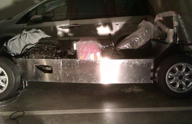
Last thing I did was to unpack the ally side panels and offer one to the car. I think I'll have a bit of a trouble fitting the rivets on the lower side of the car, probably will have to tilt it a bit. But with the side panel on, it looked a lot more... Finished!

I still have to make my mind if I want to cut the driver's side panel in half and hang the front part with rivnuts to allow "easy" access to peddles, brake fluid reservoirs and engine oil filter or if I rivet it all and hope for the best.

Sunday, February 17, 2013

Suspension Setup - Feeling Dumb

Today's goal was to set up at least the rear suspension. Before taking the wheels out I checked the camber and it was -0,8 and -1,3 on the driver's and passenger's sides, respectively. Used a nifty app on my Android to measure it against the wheel. After jacking up the car and taking the wheels out, the camber was different (and positive) since the suspension did the full drop. I made the calculations and (I hope that I managed to) set up the correct amount on the passenger's side to have -0,8º each side.

Then did lots of measurements to try to calculate the toe-in. Currently the rear has massive toe-in and the driver's side more than the passenger's side. But I couldn't make it with just the pen, paper and phone calculator that doesn't even do square roots. After much cursing and thinking, ended up storing the wheels away and left the car on axle stands on the rear, calling it a day. At home with a protractor and some scale drawings I'll manage it.

In between I recalled an old email from Steve from Aries where he advised me to have the washers on the base of the rear uprights all on one side (the front one, if I'm not mistaken). At the time I didn't pay much attention and placed them where it made easier to assemble the thing. Now I realize that it impacts castor and I'll eventually correct it when I get around to disassemble the uprights to fix the toe. That means I'll have to redo camber and after that re-check that toe is still correct. Sometimes cutting corners ends up giving a lot more work. And today I'm feeling pretty dumb with the math.

Sunday, February 10, 2013

Tunnel Done!

Started another session with nail varnish on hand. Used it to mark the prop-shaft bolts so that later I can check if they are coming loose. I wonder if, when the prop is full of road grime, I'll be able to see the orange varnish I used... Hope so! It was fun that, after releasing the hand-brake and putting the car in neutral, I could push it back and forth (to rotate prop and reach all bolts) with just one arm, while kneeling next to the car.

Then, finished the work on the big panel of the driver's side tunnel. Last time I left it with the last rivnuts already in and just needed the dremmel to enlarge a couple of the holes to get the bolts in. Did so and also tightened the gear lever pivot again.

Then I released the throttle peddle, that is actually what holds the complete bulkhead to the chassis. Pushed it all together to the side so that I could fit the small panel and drill to fix it. Turns out that the panel needed an extra part cut out if it was to go in without taking the other panels out. Used the dremmel with a cutting disk to start the cut, then bended until snapped the part and used a big metal file to make it all clear. Held the part in place with a clamp, drilled, removed it, enlarge holes, fit rivnuts and the job was done. This is the end of the tunnel! (at least until I get around to make a vinyl cover for it.
It's odd, but I look at it and it looks bad, on the pictures it is actually OK. I'm probably comparing what mine looks with what I see of other in pics, so maybe it's not that bad... But I can't wait to get it all covered anyway.

Last bit was spent making a first attempt to measure the current toe-in of the rear wheels. It was enough to test what I have and may still need to perform a proper setup (material-wise). It also made me think that I need to get my trigonometry straight before I go work on it again.

Sunday, January 27, 2013

More Work On The Tunnel

Another 2 and a half hours spent working on the car, all dedicated to the driver's tunnel panel. Only got the rivets for the bigger "half" of the panel in place. The small part that will require taking the throttle peddle out will have to wait for next week. Also filed and deburred an edge of the panel that was a bit too big near the rear. No pictures because it would look like the ones from last week. Not very motivating.

Drilling the holes and having to make effort in odd positions made very noticeable how out-of-shape I am. For a couple of holes had to stop twice to rest before the hole was drilled. Maybe I'm also needing to sharpen my drill bits.

Next week the plan is to use some paint to mark the prop bolts to guide me later when checking for bolts coming loose. Then it's the small panel. Further away... Finish tidying up the wires on the engine bay, align rear wheels toe (maybe fronts also, if they need) and tighten the wheels correctly. Then, outside panels.

Sunday, January 20, 2013

Driver's Side Tunnel Panel

First, a note on the number of rivnuts to hold the panels in place. For what I read online (should have looked for this before) was that these panels aren't structural. As such, they don't need to be spaced at 10cm. Some people even just put a rivnut in each corner. So, the passenger's side will remain with one rivnut each 20cm and the driver's side will get the same treatment.

Started the session by finishing off the passenger's side. Enlarged a bit the panel hole for the gearshift pivot bolt to get in. Took some time fiddling with the gearshift to get the bolt in, but made it.

Then tried fitting the driver's side panel but wasn't able. I've been assembling parts of the car in an order that is not the usual one. This has allowed me to drive the car sooner. It has caused difficulties in several other occasions. This is one of them: the peddles and the panel shape make it impossible to go in. Since disassembling the peddles is out of the question, I had to look for an alternative. Cutting the panel under the dash allows me to get it separately and it will go almost unnoticed. Out with the cutting disk for the dremmel, drew a line and cut the panel in two.

The big part fits nicely and still got three rivnuts pressed in the chassis during this work session. The small part still does not fit. At least now I believe the panel can get fit by just removing the throttle peddle, which is not that bad. I'll have to remove it anyway to get the scuttle permanently fixed. Below a picture of the big part in place and the hole for the small part, another with the small part on the left and how the big one looks in place.
So, this side will still take another session to get finished. And probably will postpone the small bit for when I get around to the scuttle and/or side panels. So that I can tackle the rear wheels toe alignment first.

Sunday, January 13, 2013

More Work On The Tunnel

Another morning spent on the car working on the panels. This time the objective was to get the passenger's side done. But before that, I modified one value on the Digidash settings. I had the "Pulses/Cycle" as 4 and it should be 2. I'm still a bit unsure on the remaining values, must see if I can get some confirmation and then I'll post them.

There was not much of a story with the panel work. Held it in place and drilled for two rivnuts. Removed the panel, enlarged the holes, placed the rivnuts, in goes the panel again, bolted down. This helps keeping the panel in place, a few more holes, take the panel out, enlarge, rivnut, panel in and bolt down, drill the remaining holes, take panel out, enlarge, rivnut, panel in and bolted down. To be perfect, only need to fix a bit the hole I opened to pass through the gear lever bolt, since it's a mm offset. Will do that next week, today was already late for lunch.
I had pre-drilled the panels with 10cm between centres. When putting the panel, it seems that 20cm centres is enough and so that is what is done. I can later on drill the remaining holes if I get told I should do it with 10cm.

Wednesday, January 2, 2013

Another Tunnel Panel

After some holidays, got three hours on the car. And was wonderful, seemed all I did went well and even quickly! I'm amazed.

Started by reading some data I configured initially on the Digidash (regarding ratios) and putting them down on paper. I'm going to ask if they are correct for this engine.

Then I grabbed the dremmel with a small deburring bit and enlarged slightly the holes that got misaligned on the panel I worked last. It was all done quickly (holding the dremmel as if it was a pen...) and the panel was finally set.

Placed some tape under the second panel for the tunnel top and located the part. Realized two of the holes I previously drilled were too much to the inside, missing the chassis rail... Anyway, marked the panel where it needed some adjustments and clamped it down. This time, used the 3mm drillbit through the ally holes to start the holes on the chassis rails. Then took the panel out, swapped to the 6mm drillbit and finished the holes. Some work with the rivnut tool and part of the panel was bolted to the chassis. Redid the two holes that were offset and also placed the rivnuts.

Last work with the deburring disk and the cutting disk on the dremmel to trim the panel where it was a bit too big. In the end, the panel was ready to fit.
Next is the passengers' side tunnel lateral panel. I'll need to buy more rivnuts... Also, looking to the "finished" work, I'm getting a lot more motivated to try to cut and stitch carpets and a leather-alike interior for the car, to cover the ally panels...