I looked for pictures online of hub carriers and wheel bearings but could find none that would help me with the task at hand. I asked for help on the locostbuilders forum and two members helped out, one with a link to a page with great instructions. Later I received an email from a blog reader pointing to the same page. Thanks to mcerd1, Dingz and Iain!
So, laugh moment... I test-fitted the "oil seals" thinking they were the "outer racers"... Now I really know what each part is. Armed with that knowledge, I went to work on the car a bit.
After a lot of hammering, I quitted without pushing any outer racer inside. When I started to apply a bit more strength, it would always pop up. Since the hub carriers are painted inside, I postponed the task to a next time. And first I'll scrap the paint off the inside walls, every micro-millimetre will help. I'll also try to get a piece of wood or harder material that may fit over the racer so that I can hammer it all inside at the same time. And try to do it on a proper hour, hammering wheel bearings at 23h30 in the night might make someone mad, even if I'm working 3 stories below ground...
Wednesday, September 29, 2010
Tuesday, September 28, 2010
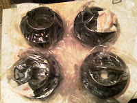
Preparing the Hub Carriers
A week and a half ago I sent and email to Steve with questions regarding the hub assembly. He replied to me on the first working day afterwards with a very detailed set of instructions.
The first step was to check the inside of the hub carriers where the wheel bearings are going to sit and check for burrs caused by tools removing the previous bearings. If found, deburr. I did so with some grinding tips on my driller.
When I was offering the bearings outer racers to the hubs just to see how hard would be to hammer them in, I got some doubts on how far they had to go in and that probably I spent the last hour deburring an area that wasn't the right one... And the right one needs a bit of work... I'll have to look for pictures of the bearings inside the hub carrier to be sure...
Saturday, September 25, 2010
The Steering Rack
My kid has been asking me to go with him assemble the car wheels so that we can make it run. I explained him there were lots of other things to be done first but, since I told him before we were going to do it together... I had to make it happen.
The two of us went for some work on the car. I thought mounting the steering rack would be something easy that he could help with. Unpacking was half the fun, playing with tools the other half.


We placed the steering rack on the car and screwed one bolt/nut, where he helped while it was still not requiring too much strenght. His attention span shifts quickly so we stopped the work and went back home. After he went to bed, I came back to finish up.
The rack had lots of play inside the mounts, the bolt holes didn't line up well... Something was missing. Inside the rack mount plastic bag there were two pieces of plastic that I had discarded as "not needed". Ends up they were spacers to put between the rack and the chassis, on the mounting points. I had to trim them a bit to fit but, after a while, the rack was mounted and with no play. I was happy and I hope the kid too.


After that work, it became clear that I'll have to reroute the brake pipe section that goes from the 4-way to the chassis, since it will get in the way of the steering arm when that gets in.
Sunday, September 19, 2010
Rear Upright Assembly (the start)
Today I planned to assemble all the rear part (minus break stuff). So I laid the inner hub, rear upright, hub carrier and outer hub. (The inner and outer hub are sometimes also referenced as rear stub axle and flange, it seems).

I first bolted the hub carriers to the rear uprights. It didn't take long to get it done.

But when I was looking into the rest, I understood something was missing there. The inner and outer hub join through the hub carrier hole, in a tight fit. But they are expected to rotate. So, some bearings should go there to help it. The box that has all the rear parts contains two wheel bearing kits, but I'm not sure how to assemble them, so I'll write to Steve.

Since I was unpacking, I went looking for the lobro joints. Also found them...
 Later back home I read that the driveshafts are held inside the lobro joints with the help of circlips. So now I know what's the purpose of some circlips tapped to one of the driveshatfs.
Since I have identified the CV joints, I believe that, when I understand how to deal with the wheel bearings, I'll have all I need to assemble the rear axle (minus the breaks). I have set as a goal to have it all assembled and in the car, including breaks and suspension, by the middle of November. Looking a bit tight...

I first bolted the hub carriers to the rear uprights. It didn't take long to get it done.

But when I was looking into the rest, I understood something was missing there. The inner and outer hub join through the hub carrier hole, in a tight fit. But they are expected to rotate. So, some bearings should go there to help it. The box that has all the rear parts contains two wheel bearing kits, but I'm not sure how to assemble them, so I'll write to Steve.

Since I was unpacking, I went looking for the lobro joints. Also found them...

Since I have identified the CV joints, I believe that, when I understand how to deal with the wheel bearings, I'll have all I need to assemble the rear axle (minus the breaks). I have set as a goal to have it all assembled and in the car, including breaks and suspension, by the middle of November. Looking a bit tight...
Saturday, September 18, 2010
Differential Supports
My goal for today was to attach the differential supports to the diff. Since fitting it on the car requires drilling some holes, I'll leave that to later, when I have all the rear axle and transmission axle in, so that I can be sure I'll drill them on the right place.
Once again, Steve from Aries made my job very easy! The supports were wrapped together and had a plastic bag tapped containing the bolts, nuts, washers and rubber discs that will hold the supports to the chassis. The nuts and washers that hold the support to the diff were screwed on the diff. It didn't take long to have it all done.


Then I unpacked the parts that will bolt onto the rear carrier (that fits on the suspension arms). I just wanted to look to the parts and see if I could understand how they go together. I think I figured it out, I'll just have to look to some pictures again. Bellow, all the parts unpacked and laid out.

If I can manage to work on the car again tomorrow, I'll put some photos up with the assembly disposition.
Sunday, September 12, 2010
Rear Break Pipe Fitted
Today I fitted the rear break pipe. There are three pipes, all labelled. The bigger one had an indication of what side should go into the master cylinder. The smaller ones only had the labelling stating they were for the rear.
I started by unrolling the big pipe. Then made the necessary bends to make it leave the master cylinder crossing under the front break pipe making sure they wouldn't touch. This was a bit hard mostly because working with a long straight pipe inside the tunnel was cumbersome. But in the end I got a result that pleased me.

Then it was a faster task of putting it through the tunnel, strapping it temporarily, making small bends to make it pass the crossing chassis tubes without touching them.

When I got to the rear, I placed the 3-way on the end of the pipe and worked from there. The smaller pipe that will feed the left rear brake was really easy to bend and place. The other one was a different story. I initially bended it in a way that made too much pipe hang away from any chassis tube, so I couldn't put p-clips on it later. So I straighten it and re-bended it in a different way, that gave me more places to p-clip it and, thus made me feel happier.

The break pipes are done. I still started looking at the suspension arms but had to postpone that. Next tasks will either be that or fitting the diff. I looked at the clutch cable but don't know on the engine where to link it. So I just ordered the Haynes Honda CBR900RR FireBlade (92 - 99) Service Manual, that I bet will be useful in many other situations, including engine tuning later on.
(2011/01/01 EDIT: Check the final pipe layout on the December posts when they got riveted. It also changed on the rear)
Friday, September 10, 2010
All Bush Tubes Fitted!
Today I had control of the hammer again so I went on into finishing the suspension arms. All arms now have the bushes and tubes fitted in and are ready to be attached to the chassis.
Again, no photos since it was the same job as before. And I was getting quite fast at it! Since it didn't require much thinking, it made me notice that it would be nice to have some music to listen while I work on the car... Have to see how to get that.
Again, no photos since it was the same job as before. And I was getting quite fast at it! Since it didn't require much thinking, it made me notice that it would be nice to have some music to listen while I work on the car... Have to see how to get that.
Thursday, September 9, 2010
Front Brake Pipes
Since my wife needed the hammer to persuade some Ikea furniture into assembling itself, I had to postpone the suspension bush tubes work and do a different task. So I laid out the front brake pipes.
As I told before, Steve sent the brake pipes cut to size, braided and labelled. The 3-way was labelled as "rear of car", so the 4-way had to be for the front. And had to take the pressure detection for the break lights. The photos on Aries site also helped me understand how to lay out the pipes and connectors.
I recall the fact that, since I'm building a LHD, things look a bit out of place from what is regularly seen on the web. For instance, my front brakes master cylinder is on the inside of the car.
So I started by attaching the pipe to the master cylinder and laying the pipe over the outside chassis tube. The inside one is "covered" by the engine, so the outside seemed the natural route. I just hope it doesn't conflict with the clutch cable.


Strapped the pipe, the 4-way and the other small pipes with plastic straps. Just got the sensor in now to cover the entry into the 4-way, minimizing the odd chance of some dirt getting inside the brake pipes.
Later on, will have to drill the holes on the chassis for the rivets from the p-clips that will hold it all in place.
(2010/09/25 EDIT: After mounting the steering rack, it became clear that the pipe from the 4-way to the chassis, on the last picture, will have to be placed in a different way, otherwise it will mess with the steering arm)
(2011/01/01 EDIT: Check the final pipe layout on the December posts when they got riveted)
Wednesday, September 8, 2010
Suspension Arms On-going
Today I didn't had much time on the car, and spent it all on the suspension arms.
First I finished putting in all the rubber bushes. Then I started on the bush tubes. There are now 5 tubes in (of a total of 20). Two suspension arms (that I don't know yet if are front or rear) are done. The rest I hope to do tomorrow. No pictures because this work does not differ in any way from the single bush and tube assembly I photographed last week.
There is a slight chance I'll hang the suspension arms on the chassis before my vacations are over...
Monday, September 6, 2010
Peddle Box is Assembled!
I finished my first "big task" on the car! The peddle box is assembled and in place. It just lacks being bolted to the car's floor (and installing the clutch stopper and the clutch cable).
Steve told me that if I pulled the gaiter out from the master cylinder, I could rotate the threaded bar. So I started by pulling them out. Later on I noticed that if I tried turning the gaiter instead of the threaded bar, it would also work.

Then I started to assemble the brake bias bar. NEVER underestimate a job's difficulty! Putting the circlips on the brake bias bar took me 1h40m and the 2nd circlip got in with my wife's help. The way I managed to spread the circlips to put them on the bar groves was using a piece of steel wire and point pliers. As stated, 1h40m later, that part was done.


The rest of the peddle box was easy to assemble. Then I got it on the car, attached the master cylinders threaded bars to the ally bits on the brake bias bar, and screwed it all in, putting the gaiters back in place.


I can now sit on my car and press the break peddle! The peddle box still needs 3 nuts to go through the floor (I need to drill the holes first). The clutch still needs a stop bolt behind. The clutch linkage is still missing. But it's my first big task performed!
(Note: still need to see if the break bias bar is skewed downwards on the inside or if after everything was properly screwed in it got horizontal).
Friday, September 3, 2010
More Peddles and Suspension Arms
I went shopping and, since I couldn't find copper grease, got some lithium grease. I also got a big rivet pliers, to save my wrists.
I spent a lot of time trying to understand how I would correctly assemble the peddle box, now that I had the grease. I couldn't get it... Since I couldn't rotate the master cylinders to screw them into the ally part (they would clash), the only solution would be to rotate the threaded bar (that I had cut a bit of) but it didn't seem to rotate. I left this task for after querying Steve at Aries again.
I then used the grease to assemble bushes and bush tube on a suspension arm. With the lithium grease, it went very easily. Steve had told me to use the metal hammer to press the metal bush tube, and so I did.


I then went around putting just the bushes on the suspension arms. Some would go in just by pressing with the hand, others needed some convincing by the rubber mallet. I still have some bushes to put in and then go over everything to put the bush tubes.
Thursday, September 2, 2010
Brakes and LHD specificities
Steve from Aries replied to me in the early hours of the day. We exchanged a couple of emails and I got all the information I needed. Steve even included some pictures to show me details on the brake bias assembly and how the throttle peddle is mounted.
So, the throttle peddle is mounted on the top, it's something to be done a lot later. But it explains why it didn't fit on the floor...
For the bush tubes, the solution is lots of copper grease. I don't have it, so I'll have to go shopping tomorrow.
The 2 thingies are called circlips and go on the sides of the bearing, in the groves. Nice! Steve warned me to put lots of grease on the moving parts too. Having grease is now a blocking issue.
Due to his explanations about the brake bias assembly and what is on the peddle box instruction sheet, a new question arose. The master cylinders should go, on a Right Hand Drive car, 0,75 on the inside and 0,625 on the outside, for rear and front brakes, respectively. And the longest thread on the break bias to the outside (right). I'm building a Left Hand Drive car... Should I mirror all instructions or assemble cyls and bar as in RHD and cross the brake pipes so that the outside goes to the back and the inside to the front? The right answer is to make it all equal and cross the pipes. Otherwise, the longest thread on the brake bias bar would have to point towards the clutch and would hit it. This was a very important information for me, since I was going to mirror it all!
While we were swapping emails, and since I didn't have copper grease, I cut the threads on the master cylinders. Used a mini-hacksaw that should be used on wood... It took me 30m to cut the threaded bit. And 30m for the other cyl. And then some more to file the tip so that the threads look nice and don't break the inside of the parts they will screw into.


After that, I opened the sealant can and installed it on the appropriate pistol. I used the sealant on all places where the steel floor or foot well panel are welded to the chassis. Maybe I'm overdoing it, since this is an open car... But I want it to be as sealed as possible.

I hope I can get my hands on copper grease tomorrow...
Wednesday, September 1, 2010
Trial-fitting the Peddle Box
Still on vacations but now back home, and with several tools bought on the last days, I started what I believe is the best first task. Out came the peddle box (clutch and brake), the throttle peddle, the master cylinders and the brake bias bar. Note the two plastic bags taped to the brake and throttle peddles. They contain the nuts, bolts and washers needed to fit those bits to the chassis! How much easier can it be?

Per instructions, I should cut off 7mm from the master cyls threaded bars. Also drill a hole on the clutch peddle. Since the hole was already drilled, I trial-fitted the master cyls and the peddle box, just in case Steve from Aries had also cut the threaded bars.
Since the engine is on the chassis, it was a bit tight to put the master cyls in. Then I placed the peddle box and then fixed the brake bias bar. The break peddle is pointing towards the back of the car, which means I need to cut the bars.


 I then tried fitting the throttle peddle but couldn't understand where it would go, since there was no room on the floor for it. After undoing and storing everything, I went around to clean the chassis and cover it.
My last task was to try fitting bushes and a bush tube on a wishbone, just to see if there were any issues, since that is one of the following tasks and there are some 20 tubes to fit. With a rubber mallet, the two bushes when in place. But the bush tube wouldn't go in any way...
Later on I was trying to figure out where 2 thingies on the brake bias bar went. Looking at pictures online I figured out I was assembling the bar incorrectly. But the 2 thingies... And the throttle peddle... And the bush tube... So I wrote an email to Steve from Aries asking those questions and with an helper photo of the 2 thingies...

Per instructions, I should cut off 7mm from the master cyls threaded bars. Also drill a hole on the clutch peddle. Since the hole was already drilled, I trial-fitted the master cyls and the peddle box, just in case Steve from Aries had also cut the threaded bars.
Since the engine is on the chassis, it was a bit tight to put the master cyls in. Then I placed the peddle box and then fixed the brake bias bar. The break peddle is pointing towards the back of the car, which means I need to cut the bars.
My last task was to try fitting bushes and a bush tube on a wishbone, just to see if there were any issues, since that is one of the following tasks and there are some 20 tubes to fit. With a rubber mallet, the two bushes when in place. But the bush tube wouldn't go in any way...
Later on I was trying to figure out where 2 thingies on the brake bias bar went. Looking at pictures online I figured out I was assembling the bar incorrectly. But the 2 thingies... And the throttle peddle... And the bush tube... So I wrote an email to Steve from Aries asking those questions and with an helper photo of the 2 thingies...
Subscribe to:
Posts (Atom)