Thursday, December 22, 2011

Steering Wheel and Wing Stays

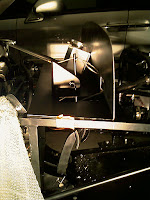
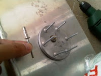
Kind of childish, but I had to get the steering wheel on. Attached the steering wheel boss, tightened the nut and fitted the horn wires through an hole. Then bolted the wheel directly on the boss. When checking the boxes to store them, found fitting instructions that stated that I should have placed an adapter plate between the boss and the wheel. Undid it all and tried to fit the plate. It wouldn't fit for anything. Bent the part just trying to get it all to fit. A waste of time. Threw the plate back on the box and bolted the steering wheel directly on the boss again. Unfortunately, the steering wheel bolts were a bit "soft" and the allen key destroyed the inside of one. The bad thing was that the bolt was half-way in. Had to use pliers to undo it. And scratched the wheel. Oh, well... Where will I find a replacement bolt like that?
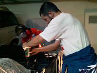
Grabbed a wing stay and read very carefully the instructions provided by Steve from Aries about how to bend them to suit my wheel size. He said on his message I should take my time and do this carefully, checking how it looks, to be sure it gets properly done. Using two pieces of wood from the crate where the car came, I bent the two stays from the (front) right wheel. I have to say that bending that iron plate is pretty hard! I still feel my arms tired. But in the end I have that stay bent. The instructions stated that I should dry fit the wing to check it but I had the wings at home.
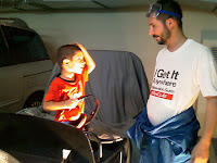
The wife and kid showed up. The kid was all happy playing with the steering wheel and it was picture time (trying to steer and use the pedals at the same time, probably not the best driving position). Then a neighbour showed up for some chat and I ended up packing and going home.
Next steps will be to bend the other wing stay, trim the edges, drill, paint and get them on the car so that I can close the brake circuit. Also put the engine airbox and the exhaust pipes. Finally, assemble the battery, charge it and wire in the ignition key. That will allow me to start the engine and see how it goes. Also need to check what I need to put the drivers seat in (bolts and nuts, I guess) so that I can later on drive the thing.

On a side note, saw on the locostbuilders forum that a MK Indy builder had a fireblade engine with the original airbox fitted and just had to make a small cut on the bonnet. That validates my decision to use the original airbox.

Sunday, December 18, 2011

On The Floor!

Time to put the car on the floor, since I need that to bend the wing stays and then to, well, try to make it work and move around!

Fitted the wheels all round, hand-tightening the nuts. Then placed the jack in the front chassis, under the radiator. With it full up couldn't reach the chassis, so I placed some wood under and jacked the car up. Always careful not to get under the car (in case it suddenly fell), removed the stays and jacked it down. The rear was harder, since the suitable chassis rails were too high. So, jacked on the side and dropped the stay height one "hole". Jacked down, went to the other side, jacked up, dropped 2 "holes", jacked down, repeat to drop 2 holes, change side, repeat to remove stay, move side, remove stay. Now... my... arms... hurt...

Then went around tightening the wheel nuts, since now the wheels did not turn when more force was applied. Well... The car would start to roll a bit, but my boot under the wheel would make it stay put. Placed a couple of wood blocks under the rear wheels to hold the car in place, since it still does not have breaks. Need to take care of that soon...

The car is a bit lower than the Mazda MX5 currently sitting next to it... It will be fun!
Then I went for the steering wheel boss. Noticed I had forgotten the nut at home (I carried it to the hardware store to get the correct fitting for it's size, to be able to tighten it). But since the wires for the horn were not long enough to get inside the boss, spent some time (and wire) making extensions. I'm feeling a lot more confident working with the electrics now, which makes me very happy!

Next time will be following Steve's wonderful and detailed instructions on how to bend the wing stays so that I can then paint them, fit them on the car and after that close the break fluid circuit.

Friday, December 9, 2011

Engine Wiring (mostly) Done

Last week I mailed all my wiring doubts to Steve from Aries and he replied with detailed instructions for where wires should go. During the week I also bought the missing terminals for the wiring work. With that email printed out and the terminals, I was confident that I could finish the engine wiring.

Before working on the wiring, I drilled four holes on the chassis to bolt my fabricated battery holder. This time I placed masking tape on the chassis, marked drilling stops with a pencil on the masking tape and then drilled over it. They were spot on and I guess this is what I need to do for all my future holes, to avoid my usual issues with "drilling with an offset". The hardest part was using my big rivet pliers under the car to rivet the part in place. But I (barely) managed it.

Going through the email Steve sent with the replies to all my doubts, I started crimping terminals on the wires lacking any. I also cut off the terminals I crimped last week to connect the fuel pump and replaced them with new terminals, since I didn't have the female type for the males that came on the loom and those I crimped were not right. Later on I cut the white that feeds the pump and used another terminal to add a new piece of wire, effectively splitting that white into two. The second wire connected to the Ignition Control Module power-in wire. I also had to replace the terminal on the loom to connect to the fuel gauge sensor, since the one that came wouldn't plug on the ETB's sender.

All that remained was to wire up earths. Using pieces of wire, connected earths from the senders and from the Ignition Control Module and Rectifier. Then linked it all to one wire with a terminal that was riveted on the chassis, together with the loom's earth. The oil temp/pressure ally casing had a small connection to wire an earth. The ally casing for the water temp didn't have such connection so I improvised a bit. Looks kind of a quick hack, might revise this later.

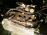
It's a bit hard to take relevant pictures of this work without going into excruciating detail. These two give a general look of the work. The first was taken from the front of the car, before earths were connected. The second was taken by the end of the day, from the side, showing up the earths riveted on the chassis and the fabricated part that will hold the battery. It's a pity that with this work done I feel that the engine bay is looking a bit of a mess, with all those coloured wires going everywhere... Maybe the fact that I haven't yet ripped off the tags on each wire doesn't help.
All that is missing, in the engine bay, is putting in the battery, connecting all lights and the two wires for the brake oil pressure. On the rear it's all about lights. This leaves the dash wires to crimp and connect to instruments. The lights will be done (a lot) later. The instruments, I'll have to see the minimum to run the engine.

Preparing to put the car on the floor, wanted to fit the steering wheel boss and wheel. Unfortunately, I don't have a socket big enough for the steering column bolt. Will have to go shopping for that. At least the tin-top socket driver has the correct size for the wheel bolts and has a connection point to add other sockets.

Running the engine is not far and then driving the car inside the garage space...

Friday, December 2, 2011

Riveting in Parts and The Wiring Work Begins!

Yesterday was a holiday and today I spent a vacation day to make a long weekend. This provided me with much needed car time! The first task of the day was to bolt the parts I fabricated on the chassis. Then bolt the coil packs to them. Bolting them to the chassis required some work with the drill because I needed the bolts to go on an angle different from the previously drilled ones, otherwise I couldn't put the nuts in place. In the end, it looks better than I thought, although it's not a great fabrication work. But it gets the job done!
Then I riveted the horn and engine oil gauge case in place. Both required enlarging the holes since I had drilled with the 4,75Ømm and the rivets were 4,9Ømm... Note on the pic the brace that holds the oil gauge's case: it has rubber to absorb the vibrations. The oil pressure sensor is very sensitive to vibrations and would collapse otherwise.
Following this, unpacked the radiator fan and took some time looking to it and the bits that come with it to hold it in place. Other people brace it to the chassis, a bit away from the radiator. I'm a bit afraid of doing that since air temp is a lot hotter here than in the UK. So I looked into getting the fan "bolted" to the radiator. For now, and since I don't know if the blade is spinning in the right direction or if I'll have to take it apart to switch, I just braced the fan with a pair of plastic wraps.
No more excuses to hold me back from crimping some terminals on the wires... That was the task I've been afraid of doing and been dragging my feet to delay. But no more!

Crimped spades on the radiator fan cable and connected it to the loom. Also connected the already crimped connectors from the loom on the brake light switch and on the horn. Then crimped the rev. counter loom wire and the matching wire that leaves the ignition control module. The wires from the fuel pump were also crimped but these will have to be redone. I believe I used too small terminals and I need to buy bigger ones, but I only understood that a while after crimping the thing.

There were a couple more wires I could have done but I need to buy more connectors. Since I knew nothing about this kind of electrics, I bought a box with some assorted connectors. Turns out they are mostly "red" (small) ones and I need "blues" of one type and "blacks" of another (wonder if these colours are the same in all western countries).
There are also a bunch of wires I don't know where to connect of switches I don't know which wire should take. Next week I expect to take the Friday as vacation again, by then I hope to know what to do. Might even get around to put the wheels on the car and get it on the floor!

Sunday, November 20, 2011

Fabricating Bits

Picking up where I left last week, fabrication was the game today. I needed to redo the strap that holds the battery to the car, since I relocated the battery, and two supports for the coil packs. It was a task that took time, specially since I measured and dry-fitted things many times. But in the end it came out almost perfectly.

The idea with the battery strap is to rivet it on the chassis rail underneath and bolt it on the steel plate in front. Taking the bolts out allows removing the battery but with them on it's there to stay.
The coil pack supports could look nicer than they do, but since I don't have ally cutters, I would have had to use the dremmel and a cutting disk to make detailed shapes. So I lazily resorted to doing these supports that although don't look that nice, do their job.
Since taking the pictures, I've visited the storage room enough to now have all the fabricated pieces painted black. Next week I just have to bolt/rivet them on the chassis (with the need to drill the chassis for the battery strap fixing holes).

Saturday, November 12, 2011

Moving Parts and Making Holes

Had some time today and started by following the suggestion made by David on the comments of my previous post. He said that the rectified couldn't stay on the bulkhead otherwise it would overheat and fail. If that happens in the UK, imagine with the 35º+ temperatures we have in Portugal during the summer...

So I had to unstrap and move the electronic control unit, then made some holes on the engine cradle and bolted the rectifier there. Some cable tidy up and it was done. This move means I can also move the battery to the front of the passenger footwell, next to the engine. It's a lot better in terms of weight balance. Although it means my previous battery strap is garbage. Took measures for a new strap. The picture shows things in their new places.
Then I tried to bolt the coil packs to the provided mounts. I don't have any metal plates to hold them, as it seems others have. My idea was to use long bolts with several nuts to bolt the packs on the mounts. Turns out I failed to measure the distance between bolts and it turns out this fails. So I ended up taking measures to later on fabricate some ally supports. Nice I bought that sheet of aluminium...

Last task was to drill holes for the coil pack supports to be made, to rivet the horn and to rivet (or should I bolt?) one of the earth terminations on the loom that I can't make reach any of the bolts around there.

Monday, October 31, 2011

Electrics - All Ancillaries Placed

Had today as vacation (tomorrow is a national holiday) and restarted with the ancillaries. Using plastic straps, tied the ignition control unit  (through the rubber braces it has on it's casing) on the chassis. Then plugged the wires, that had all been labeled by Steve from Aries. Also plugged the specific ones to the coil packs.
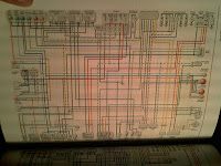
Next, placed the rectifier roughly around where it will lay and plugged the other cable that came on the ancillaries box. That cable wasn't labeled but most of the wires are easy to tell, specially with the help of the Haynes Manual wiring diagram. So, the rectifier cable was connected to the alternator and to the positive cable that attaches to the battery, with the fuse box in between. Bellow is, besides the part picture, also one of the diagram.
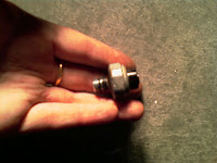
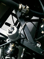
One of the gauges missing was the oil pressure sender. First I had to remove from the engine the old pressure switch. Then connected in it's place the braided hose that came on the Digidash box. Pictures show where the braided hose connects to and the looks of the removed pressure switch. On the end of the braided hose there was a casing with two tappered holes, one for the oil pressure sender and another for the oil temperature sender. The third picture shows that and also the water temp sender on it's casing, on the radiator pipe.

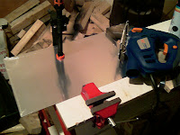
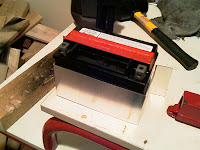
The battery needs some secure way of being held to the car. I've bought a small sheet of ally and the last task of the day was to make some straps. Only one got finished and both will still have to be painted black, but it seems I'll be able to make this one work too. The job at hand was split in two phases: first clamp the sheet down to cut it with the small electrical saw. Then, using a piece of wood and the rubber mallet, bend the metal cuttings to wrap around the battery.
Next time, tasks will be to bolt (or rivet) down the ancillaries, senders and the horn. Also to bolt down the radiator fan. Then will have to crimp cables...
I must take this chance to thank Iain and David for having given me access to their build pictures. They have helped me much and at the current build stage there was lots of information I got through your pictures!

Friday, October 28, 2011

Electrics - Coil Packs

Had some time off work and spent a bit on the car. Took the decision to install first all the engine ancillaries and only after that work on crimping electrical connections to the wires and attach them. It seemed the easiest task to start with the coil packs and the HT leads.
Using the Haynes Manual for the CBR900RR as a helper, figured out (after one hour of reading) which coil pack controlled each "pair" of sparks. Each coil pack had scribbled the colour of the wires for each connection. Matching those colours with the wiring diagram, figured which one was for the #1 and #4 cylinders and which one was for the #2 and #3.
Still looked around where to put the ignition control and regulator but ended up packing for the day.

Wednesday, October 19, 2011

Continuing on Electrics

After spending the weekend at work, today I had the day off as compensation (although having to be reachable). So I got to spend a bit of time on the car.

Just finished laying down the electrical loom and hold it in place with plastic straps. Also looked into the battery, to get it's size, since I need to make/buy some brackets or another way to hold it in place. Found out it's very tiny and the acid is all outside for me to fill it when I get around to use it. Took the engine ancillaries with me but didn't get to lay them on the car; that will have to be done another day.

I'm stalling a bit, it's something daunting to me. I also have to figure out what I need to buy, in terms of plugs and connectors. I'll probably only have the electrics done by the end of November, at this pace. I still hope to get a second compensation day next week, that might help speed up things a bit.

Saturday, October 8, 2011

Header Tank Fixed

Only had an hour and a half, but got a task done. Drilled the holes on the header tank and then on the bulkhead to hold it. This time, to avoid a wrong selection of drill bit sizes, I used the one of the washers to take the measure for the right drill bit (6mmØ).
It would had been easier if I had drilled the holes on the header tank prior to attaching the stiff tubes on it...
The kid was around when I was packing up and taking the picture for the blog and wanted his car to appear. Oddly enough, it's not one from "Cars" movies!

Before packing, I still had time to start laying out the electrical loom on the car. I have spent a couple of nights with the loom all spread out, labeling each wire. Now was the time to get it on the car. It is not all in, but that will be continued. The idea is first to just use plastic straps and later on use the riveted p-clips, when the location is final.
Feeling a childish urge to fit the battery, the steering wheel, the horn, wire it all up and start honking...

Sunday, October 2, 2011

Throttle Peddle in Place!

Did not have much time and spent it all around the throttle peddle and the bulkhead. Drilled the peddle for the cable to hold on (forgot about that last session). Then marked on the peddle where I should drill for the bolts and drilled that. Lost a bit of extra time since I still can't figure out the drill bit diameter by looking at the bolt. So drilled the 4 holes with the 3,5Ømm, then enlarged with the 4,75Ø and ended up enlarging again with the 6Ø for the correct size...

Having the peddle drilled, placed the bulkhead on the car and fixed it with masking tape. Marked using the peddle holes where to drill there. It was all positioned in a way that ensured two of the wholes would be on a chassis bar, to stiffen the peddle attachment. After marking, when I was about to drill, the wife and kid arrived from the playground. He wanted to help me using my gear. After properly geared, he pressed the driller trigger while I held it in place. He drilled the 4 holes (except the final bit on the two that went through the chassis, when the drill bit sometimes gets stuck).
He then left and I just had to bolt it all up and connect the cable. I then sat on the car pressing the peddles and testing it all. It really is a tight squeeze on the peddle area, specially because I like chunky footwear. I will probably have to buy some "All-Stars" or karting boots to drive the car. And really considering a trick on the footwell suggested by a cousin, to give me a couple more centimeters. I might also have to make a new hole for the cable a bit lower. Since the current one is too high, the peddle is sensitive (travels half the distance that my tin-top one travels)...
As visible on the pictures, I spent a bit of time during the week spray painting the bulkhead black. It's far from perfect, but looks a bit nicer than raw ally.

IMPORTANT NOTE TO RHD builders: I can have the throttle peddle in that position because the right side has the 2 holes on the chassis tube that makes the top of the tunnel. RHD builders must position the peddle as further back as needed to be able to bolt the two back holes to the horizontal chassis tube, since there is no outer tube available to bolt the any of the sides to. Failing to bolt two holes to the chassis will make the bulkhead ally flex every time the peddle is pressed.

Sunday, September 25, 2011

Throttle Peddle and Electrics

Picked up where I left last time. With my new dremmel-like tool, cut the hole previously marked on the bulkhead. That allowed me to get the throttle peddle in place. Cutting and cleaning took the best part of an hour.

Then I had to drill a hole on the peddle to get the throttle cable through. Since I don't have a pillar drill, I was a bit affraid of this task. But since the dremmel has been solving all issues I throw at him, I tried it. Tightened the peddle on the vice, on an angle to aid movement. Placed a 1mm drill bit on it and some cutting oil and started a small hole with the dremmel on slowest speed. After having a bit of a hole, swapped the drill bit for a 2mm one, that matched the cable diameter. Constantly checking that I had the drill on a perpendicular and straight position to the peddle, and putting oil once in a while, got a clean hole. Dry tested it on the cable and it was perfect!
Packed up and went home. Later on, untangled the electrical loom on the living room floor and looked at it with the wiring plans in hand. The loom (and diagram) looked a lot more frightening inside the bag than all spread out on the floor. With some masking tape, started labeling each wire, to make it easier to connect when I get the loom on the car. Only marked all the rear wires, the rest will have to be done another day.
I'll have to see about putting some black paint on the bulkhead and then attaching it to the car, with the thottle peddle on. And then cable tie the electric loom and start connecting things...
Monday, September 12, 2011

Fuel Circuit Done! (And Other Bits)

Today, being on vacation and with the kid at school, I had almost 6 hours to work on the car, interrupted only by lunch. I'll cover both work sessions on the same post as if they were one.
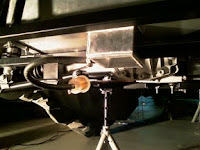
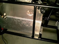
The gas tank was ready to go on the car and that was my first task. Placed the fuel sender on the previously drilled hole and then applied 6 rivets to hold it in place. Did not put the recently acquired Nural stuff on it since, after reading the small letters, it should be used in replacement of rubber seals; the sender had a rubber seal.

Once in the car, marked the drilling spots and drilled tank supports and chassis. When I grabbed the bolts and washers, noticed the washers were quite large and two of the drilled holes were too close to the tank wall for the washers, so I re-drilled and bolted the tank down.

Spent some time cleaning the floor of all the ally and steel bits from that drilling session (and previous ones) with a broom. After that I attached the rubber pipe from the tank to the copper pipe that runs along the car. I had to lay on the floor, hence the time previously spent cleaning... After taking the picture I tied the pipe to the chassis with a plastic strap, to be more certain it will not run on the road. (EDIT: 2012/09/29 - I should have cut 12cm of pipe from what was provided because it was too much and later on I needed that to close of the tank)
After lunch break, grabbed my Haynes CBR manual and looked where I should attach the throttle cable. It said I should take the carbs off the engine head, but that was a task I didn't look forward too. After 30m fiddling with tools and cable on a (very) tight space, I managed to hook the cable in place without taking the carbs off! Very happy with that. To close the fuel circuit, attached the tubes that leave the fuel pump to the copper line and to the carbs intake. Again, it helped to have the Haynes manual. It was also very helpful to have all tubes labeled by Steve from Aries. As usual, great job of him that made my life easier! Tied the pump to the chassis with a couple of cable ties and the job was done.
Next I grabbed the nosecone, scuttle and engine cover and trial fitted it all. First the cone and scuttle, holding it to the chassis with masking tape, to avoid more damage as I did previously. Then the engine cover, which required moving the scuttle a bit. This allowed me to mark the definitive place where the bulkhead will sit. It also gave me the chance to take the great picture bellow! Marked the correct location for the bulkhead so that I could remove it for further cutting.
Stored away the fiberglass parts and spent a load of time marking on the bulkhead where to cut to be able to put the throttle peddle. Closed the day with the bulkhead marked but uncut. More dremmel action soon!

Sunday, September 11, 2011

More Dremmel Cutting on the Bulkhead

Last time I had left the trimming of the bulkhead unfinished. Today I went to the storage room to fetch some boxes (unrelated to the car) and I saw the bulkhead on the table, the tools ready to be used... Although it was over 23h00, I couldn't resist the urge, plugged the tool and finished the trimming job. It took me around 45 minutes to finish the trimming and enlarge the hole I previously made for the steering column.
No pictures, but a small task out of my way in order to move forward with the bigger (and more visible) tasks.

Friday, September 2, 2011

Refrigeration Circuit Done! And Other Bits...

Went to the car with the radiator, nosecone and refrigeration fan. Clamped the radiator to the chassis, trial fitted the nosecone and fine-tuned it's position. Removed nosecone and confirmed that I can attach the fan on the chassis later, without removing the radiator. Steve said I could brace the fan to the chassis, although there is a gap, refrigeration works well. Since Portugal has around 10º/15º more on the summer than the UK, I'm still unsure if I'll attach it that way or in a different one. Anyway, since that will be later...

With the radiator clamped, it was impossible to mark it for drilling, since the clamps were over the drilling areas. But the radiator is such a tight fix inside the cone that I was unsure how to do it. Ended up solving the issue the following way... With the radiator clamped, checked there in the chassis supports I should drill for best fit (offset to the interior on the upper ones and offset to the exterior on the lower ones). Removed the radiator and drilled the chassis. Then placed some paper masking tape on the radiator and clamped it on top. Fit the nosecone to ensure positioning. From behind, used a pencil to mark the radiator where to drill, putting the pencil through the holes in the chassis supports. Remove nosecone and radiator, drill, place masking tape on the top area, fit radiator (with bolts on the lower supports), fix nosecone, mark from behind the top holes on the masking tape. Remove cone and radiator, drill, attach radiator with the 4 bolts and nuts, trial fit nosecone to ensure success.
Having the radiator in place, attached the remaining hoses to it. One of them had to be cut to insert the therm sensor housing case. After taking the picture bellow, covered the casing hole with some masking tape, since I didn't have the sensor with me. With this, the refrigeration circuit is done!
Last task that I started was to trim the bulkhead, since it has a bit of excessive ally on the lip that prevents the hood to be correctly placed on top of the scuttle. Cutting ally with the dremmel is very time consuming and I had other things to do, so had to leave the job incomplete.
All the above tasks, including some cleaning up of the area around the car, took me around 3h and a half.

Thursday, September 1, 2011

More Work on the Fuel Tank

After two weeks away at the beach with the family, came back and had some car time. Spent the evening around the fuel tank. A couple of weeks ago I had to buy fixings for the sender on the tank. Ended up buying big enough rivets, after looking for rivnuts but not finding adequate ones. Also bought a squirt of Pattex Nural 61 to use around the sender.

Using the sensor, marked the 6 holes to drill on the tank. The box of rivets came with an HSS drillbit of the correct size (4.9Ø). Then drilled the holes and trial-fitted the sender.
After that, the only thing needed before fixing the sender was to clean the tank. For that, I had bought a jar with 5 liters of petrol. First closed all the holes except the sender one with parts of a plastic bag and rubber bands. Cutting a long story short, rubber bands break with petrol, had to redo the closings with string. Did the washing on the bathtub, scratched it when hitting it with the tank. Placed the rubber mat on the tub's floor to prevent more scratching and the mat is now all wrinkled because the petrol attacked it (wife happy because she wanted a new mat for that bathroom and now has the perfect excuse).
Drained the tank as best as I could I left it to dry. When dry, I'll be able to fit the sender and put the tank on the car. What seems an easy task took me, including the time to clean up the balcony and the bathtub, almost 3 hours.

Thursday, August 11, 2011

Celebrating One Year

Small note to celebrate the first anniversary on receiving the kit. One year ago around this hour I was returning home after delivering the rental van on the depot, feeling completely drained of energy but very happy.

Looking back, I'm sorry I haven't kept a clear record of hours spent on the car. It would have been enough to write down how many hours in each post... Probably have spent around 250 hours so far, but it's more of an educated guess. Could have spent a lot less if I had done the right thing 1st time, had all the proper tools on the 1st attempt, etc. But it's all part of the learning process and one of my goals is to learn a bit about mechanics.

All in all, a wonderful adventure, that allowed my to meet new and great people, learn, have fun, have a project. Thanks to all that helped, supported or inspired!

Saturday, August 6, 2011

Additional Cutting of the Bodywork

I'm loving the dremmel. But since it is borrowed, I thought it would be best to perform as many jobs with it as possible until I have to return it. So, instead of drilling for the radiator, I thought it would be best to trial-fit the bodywork so that I could shave off excess to make it fit well and also to use the dremmel on the bulkhead (specially so that I can have a throttle peddle).

The scuttle had to be cut on one side, in the interior lip, to accommodate the arch where the steering column attaches to. This was a quick job.
More cutting had to be done on the nosecone to make way for the nosecone attachment parts and also to clear the way where it was hitting slightly the radiator mounts.

In the end couldn't mark the bulkhead's final place since the engine cover part lost it's curve after laying on the floor for a year. I had heard about glass fiber loosing a bit it's shape after some time. Being kept on a room that exceeds 35º in the summer... I guess I should expect it. Notice the picture where it looks too "straight", without the curve.
Although I didn't mark the bulkhead's location, I noticed that it needs some trimming specially in front of the drivers. After trimming it, I'll hold the nosecone and scuttle in place with tape and then, even if the engine-cover is not with the right shape, I'll be able to check where the scuttle shall lay. But that will have to wait for the next weekend.
Oh, and holding the nosecone and scuttle in place with tape will really be a must. After taking this picture I tried to get the engine-cover roughly in place and ended up pushing the nosecone. It dropped on the cement floor, and it now has scratches in two different (and visible) places. :( I hope I can get some wax and/or another material to cover up mistakes I'll be doing along the build.